
Introduction
This centrifuge is 3D printed by hand using a 3D pen. It achieves an acceleration of about 400 × g using a 18.5 V laptop charger.
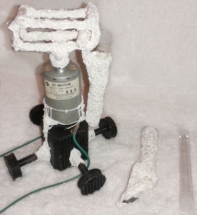
The picture pretty much shows the design. The test-tube holder arms are detatchable, which means they can be replaced if a larger radius is required, or if a different size of test tube is to be used. Each arm forms a hinge with the rotor frame to allow a swinging-head design. The arms do catch against the frame, which less of a problem than you'd think. Regardless, it could be solved by adding a circular guard.
Much of the base (in black) is made from parts that were originally printed for another project before its design was changed. The motor was salvaged from an old appliance (I can't remember what). Since most of the parts are recycled, the cost of the centrifuge is probably less than a dollar. Even without using recycled parts, this project could probably be built for less than $5.
If you decide to make your own centrifuge:
WARNING: Make sure you have a safe place to use the centrifuge!
It may cause injury or damage if it fails as there is a danger that
the centrifuge may break under load and eject shrapnel at high
speed.
Printing with the 3D Pen
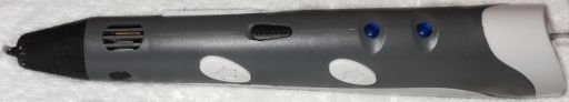
I built this project using a 3D pen extrudes plastic (in this case, PLA) filament like a 3D printer, but is controlled by hand.
My friend offered some suggestions on how to use the 3D pen to make the centrifuge. In particular, his suggestion to form the test-tube holder by wrapping it in paper, and printing around that proved very successful. The build process is roughly:
-
Print the test tube holders.
For each of two holders:
- Print around a paper-wrapped test tube to make a tube form. Leave a centimetre or two unwrapped to allow the test tube to be removed easily. The test tubes are about 110 mm in length (including the cap), and 12 mm in diameter.
- Print an arm rod and a hinge rod. To print the rods, I extruded a single strand of plastic along a flat surface until it just started to curl. I let it cool, and extended it to the desired length. Then I added more layers until it was the desired thickness. The hinge rod is about 45 mm long. The arm rod is about 40 mm long.
- Weld the arm rod to the tube form (using the 3D pen). Make sure the arm rod is straight and long enough to clear the test tube.
- Weld the hinge to the end of the arm rod. Make sure the hinge is at 90 degrees to the arm rod.
- Optionally, mark one of the holders so you can tell between the two. This is useful when working with a single sample (and a counter-balance). I marked mine with a small piece of electrical tape.
-
Print the rotor frame.
You should be able to see how the frame is welded together in
the picture of the centrifuge.
The perpendicular rods are arranged with one at the bottom in
the centre to mount onto the motor, and two at the extremeties
on top.
There are no perpendicular rods at the extremeties on the
bottom, as this would prevent the test tube holders from being
attached.
- Print the rotor frame rods: three perpendicular rods, and four radial rods. The perpendicular rods are about 40 mm long. The radial rods are about 70 mm long.
- Print a plastic rod between two of the radial rods at one end to form a vertical rod. Repeat at the other end, and for the other two radial rods. The height of the vertical rods are about 30 mm.
- Weld the perpendicular rods to the frame.
- Attach the rotor frame to the motor. The motor I used has a metal helical gear. The gear provides the means for the motor to firmly attach to the frame, as unfortunately PLA does not stick to metal. Forming the PLA around the gear was tricky, and required a few attempts. I suggest placing a tube of paper around the gear, leaving a few millimetres between the gear and the paper. The PLA can then be extruded into this gap. To prevent the helical gear from pushing the rotor frame off the motor (without worrying about direction of spin), I printed under the gear too. Once you have a PLA attachment for the motor, it should be welded onto the rotor frame.
- Make the base. For my centrifuge, I welded together some unused parts from another project. The exact design of the base is not important so long as it is sufficiently tall, and stable. Ideally, the test tube holders should not catch on the base during spin-down.
- Attach the motor to the base. To do this, I printed around the motor, and onto the base. I ran out of PLA at this point, but it turns out that very little is needed to keep the motor on the base. That said, it'd probably be safer to use more (see the warning above).
Measuring the Acceleration
The acceleration provided by a centrifuge can be calculated using
the equation
 from
this Wikipedia page.
To determine the acceleration, we need to know the radius and the
spin speed.
The first of these, the radius, can be measured easily.
In the case of my centrifuge, the radius is about 130 mm.
from
this Wikipedia page.
To determine the acceleration, we need to know the radius and the
spin speed.
The first of these, the radius, can be measured easily.
In the case of my centrifuge, the radius is about 130 mm.
Measuring the spin speed is a little trickier. I used a photo-transistor and infra-red LED as a photo-interruptor. The signal from the photo-transistor has to be amplified to be readily measured, such as with the following circuit:
Each time one of the test tube holders passes between the LED and the photo-transistor, it generates a pulse that can be measured with an oscilloscope. A half-rotation of the centrifuge takes 18 ms. That equates to 1667 RPM.
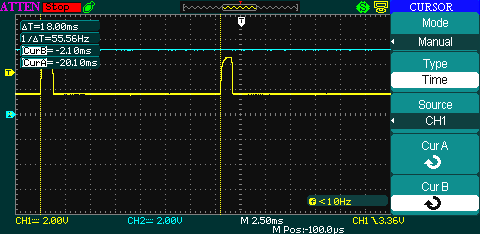
Putting 130 mm and 1667 RPM into the above formula gives 404 × g.